


Design, Test, and Implement Control Systems
|
Control system engineers use MATLAB and Simulink at all stages of development – from plant modeling to designing and tuning control algorithms and supervisory logic, all the way to deployment with automatic code generation and system verification, validation, and test. MATLAB and Simulink offer :
|
|
Using MATLAB for Control Systems


White Paper
Model-Based Design for Embedded Control Systems
 DOWNLOAD
Model and Simulate Plant Dynamics
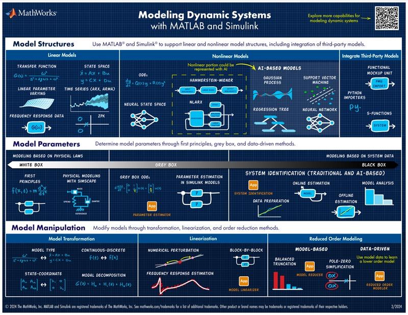
Use MATLAB and Simulink to build accurate plant models. Describe the complex dynamics of your plant using a variety of supported modeling approaches, and use the most appropriate approach for each component in your plant to create the system-level plant model.
Create complex multidomain plant models without having to derive the underlying first-principles equations using physical modeling tools. Simscape models have a layout that matches the structure of your physical system. Assemble the model by connecting components from electrical, mechanical, fluid, and other physical domains into a network. Alternatively, when you do not know the detailed structure of the model, estimate linear and nonlinear plant dynamics from input-output data using system identification, including AI-based techniques. Create AI-based reduced order models of components modeled with full-order high fidelity third-party tools..
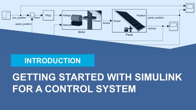
Design and Tune Feedback Compensators
Analyze and develop closed-loop compensators, and assess key performance parameters, such as overshoot, rise time, and stability margins. Trim and linearize nonlinear Simulink models. You can also model and analyze the effects of uncertainty on the performance and stability of your models.
Take advantage of Bode plots, root locus, and other linear control design techniques and automatically tune PID controllers in a simulation model or on test hardware. Prebuilt tools let you automatically tune decentralized multivariable controllers and leverage advanced control strategies, such as model predictive control and robust control. Use optimization methods to compute controller gains to meet rise-time and overshoot constraints.
Improve the performance of complex systems by using AI-based and other data-driven control techniques. Use data-driven control algorithms to develop controllers that learn and adapt to changing dynamics and for scenarios when analytically deriving complex nonlinear dynamics is not feasible.
Design and Simulate Supervisory Logic
Use Stateflow® to model, design, and simulate the supervisory logic in your control system, which schedules the operation of the controller, controls the operational mode of the system, and performs fault detection, isolation, and recovery (FDIR).
Use the graphical editor to build your logic as a state machine or a flow chart. You can also combine graphical and tabular representations, including state transition diagrams, flow charts, state transition tables, and truth tables, to model how your system reacts to events, time-based conditions, and external input signals. Visualize system behavior during simulation by using state diagram animations to highlight the active states and transitions in your model.


Deploy Designs to Embedded Controllers
Once you have designed your control system algorithms, you can refine them for implementation. You can specify the fixed-point data type properties of your design to prepare it for implementation with fixed-point arithmetic. After verifying control algorithms in closed-loop desktop simulations, deploy them to production microcontrollers, PLCs, and FPGAs by automatically generating C, structured text, or HDL code.
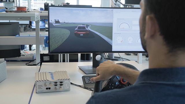
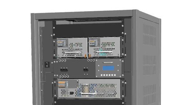
You can continuously test and verify your control system. Conduct hardware-in-the-loop (HIL) testing by running the control algorithm on an embedded controller and running the plant model in real time on a target computer connected to the controller. You can further verify and test your control system using formal verification methods.
Contact Us
If you have any enquiry, please do not hesitate to contact us.
Contact Us
